Reliable Tile Installation on Problematic Substrates
By William M. Carty, Ph.D. and Peter A. Nielsen Presented at Qualicer, Castellon, Spain
Centuries ago, European builders developed a reliable means of installing tile for high-traffic, high-use applications which relied on the laying of a sand strata between the structural substrate and the mortar-bed/tile composite top layer. Due to space (height) requirements and other concerns, the sand strata method for tile installation is, for all practical purposes, extinct. Modern theory, however, explains that the sand strata "uncouples" the tile from the structure, allowing structural movement without damage to the tile layer. Approximately fifteen years ago, a modern analog of the sand strata system was developed in which a thin, polyethylene sheet membrane with a grid structure of square, cutback cavities and an anchoring fleece laminated to its underside, functions as the uncoupling layer. This article will provide the basis for the claim that a configured membrane allows the normal loading forces exerted on the tile surface to be widely distributed through a forgiving shear plane, similar to that which would be expected in the sand strata. These results contradict other work and theories which suggest that extremely strong bonds are necessary between the tile and substrate to maintain a crack-free tile surface. In fact, it is proposed that a weak interface is more forgiving, allowing substantial movement in the substrate without any evidence of cracking in the tile or the grout joints. This system also allows differential expansion and contraction between the tile and the substrate and can be used on a wide range of substrates which have traditionally been viewed as problematic; including plywood, OSB, post-tension concrete slabs, green concrete, radiant heated floors, and gypsum underlayments. To understand how this system accommodates stress within a tile assembly, the stress-strain relationship for materials under load will be reviewed, followed by a ceramic matrix composite analogy that illustrates how stress buildup and stress reduction are possible within composite layers. The shortcomings of directly bonding tiles, or setting tiles in a force-conductive assembly, will be evaluated in the context of large-scale tests performed on tile directly bonded to concrete slabs. Finally, it will be demonstrated that an effective means of "uncoupling" the tile covering from the substrate, fundamental to successful tile installations, can be achieved in a contemporary thin-bed application.
The primary challenge the tile industry faces is successfully joining or marrying the various components that make up a tile assembly, components that are not only dissimilar in their physical properties, but in their function as well. Traditionally, each component or layer of the tile assembly could be divided into four distinct categories: 1) structural elements, 2) substrates or bases, 3) bonding materials and joint fillers, and 4) the ceramic tile layer.
Ceramic tiles are the veneer components of the assembly that function not only as decorative treatments, but as a working surface of the finished building environment. Because ceramic tiles are hard, brittle, and unforgiving materials, they are dependent upon the dimensional stability of the assembly to which they are bonded before they become a viable surface covering.
Movement forces are present in all tile installations due to the dimensional instability of construction elements that make up the assembly. Dimensional instability is largely a function of changes in moisture content, temperature, and loading (both dead and live loads) of the construction elements themselves. The resultant forces can be classified as compressive, tensile, and shear and manifest at the shear plane or material interfaces of the tile sandwich. It should be noted that these forces occur in combination.
Analysis of the physical properties of each material in the tile sandwich dictates that an intermediary component, one that will allow independent movement between the tile covering and the building structure without contributing a stress dynamic of its own, is necessary to achieve a crack-free tile surface.
Centuries ago, European builders developed a reliable means of installing tile for high-traffic, high-use applications which relied on the laying of a sand strata between the structural base and the mortar bed/tile composite top layer (Figure 1). The sand strata was the intermediary component that uncoupled the tile from the structure, allowing structural movement without damage to the tile layer. In addition, it allowed the normal live load forces exerted on the tile surface to be widely distributed throughout a forgiving shear plane.

Figure 1
A schematic cross-section of the traditional method for uncoupling the tile from the substrate - the sand strata method.
A more recent analog of the sand strata method is a wire-reinforced mortar bed over a slip-sheet or cleavage membrane. As shown in Figure 2, the principle elements that make this type of installation viable are: 1) the mass of the mortar bed holds the floor section to the structural base; 2) the mortar bed provides an effective load distribution plane, allowing normal live load forces exerted on the tile surface to be widely distributed throughout the assembly, and 3) the cleavage membrane isolates the entire floor section from the structural base, preventing stresses in the building structure from telegraphing through to the tile covering. However, the principle disadvantage of this system compared to the sand strata method of installation is that the mortar bed can contribute to the assembly its own dynamics (e.g. shrinkage during the hydration process, thermal expansion and contraction, curling, etc.), which can lead to damage of the tile covering.
Nonetheless, due to many factors (e.g. assembly height and weight, which, in most cases, affect the structural design requirements of today's building environment; economic viability; the shortage of skilled labor; and the demand for simplification of the installation process), the sand strata method for tile installation and its more recent analog are, for all practical purposes, extinct.
Today, the landscape has changed dramatically. The most fundamental change our industry has undergone in the last millennium has been the shift from the traditional mud-set installation to the thin-bed or direct-bond method of installation, as illustrated in Figure 3. The implications of this shift are profound and far-reaching.

Figure 2
The more recent approach to the sand strata method-the wire-reinforced mortar bed over a slip-sheet (cleavage membrane). The wire has been omitted for clarity.


Traditional wisdom has always maintained that an intermediary component that allows for independent movement between the tile covering and the building structure, without contributing a dynamic of its own, is necessary to achieve a crack-free tile surface. In light of this, contemporary wisdom states that an extremely strong bond between the tile and substrate is all that is needed in a directly bonded system to achieve a crack-free tile installation. The problem with this line of reasoning is that the contribution of each layer in a traditional system to the system's overall mechanical viability is either ignored or not addressed.
Approximately fifteen years ago, a modern analog of the sand strata system - one in which a thin, polyethylene sheet membrane with a grid structure of square, cutback cavities and an anchoring fleece laminated to its underside, functions as the uncoupling layer (commercially known as "DITRA") - was developed. The configured membrane, illustrated schematically in Figure 4, allows the normal loading forces exerted on the tile surface to be widely distributed through a forgiving shear plane, similar to that which would be expected in the sand strata. This system also allows differential expansion and contraction between the tile and the substrate and can be used on a wide range of substrates which have traditionally been viewed as problematic; including plywood, OSB, post-tension concrete slabs, green concrete, radiant heated floors, and gypsum underlayments. To understand the mechanisms of this system, one must first evaluate the relationship between stress and strain.

Figure 4
The modern analog to the sand strata method. The image on the left illustrates the configured nature of the polyethylene sheet, with the polyethylene fleece bonded to the bottom. The right shows the membrane in a typical installation, serving to uncouple the tile layer from the substrate, allowing the tile assembly to act independently from the substrate.
Stress-strain relationship (a brief introduction)
To provide a basis for evaluating the various bonding systems, and the causes of installation failure, it is necessary to briefly review the importance of the stress-strain relationships for materials under load. Figure 5 is a typical stress-strain relationship for a ceramic (brittle) material. There are basically two ways of approaching the stress-strain problem: 1) from a perspective of the applied stress; and 2) from the viewpoint of the strain within the material.
The first approach is probably the most common, viewing the problem as dictated by the applied stress. Under an applied stress, a strain is developed, following an elastic behavior. This means that the strain is proportional to stress and that upon unloading of the specimen, the sample returns to its original dimensions. For brittle materials, the elastic behavior model reasonably describes the deformation behavior. In addition, defects or flaws within the material represent stress amplifiers; the magnitude of the amplification is dependent on the orientation and morphology of the flaw. The weakest link theory, as frequently used to describe the mechanical behavior of chains, appropriately states that the largest flaw dominates the strength of a brittle material. The presence of tensile stresses is often difficult to discern, as the stress state within the material is dictated by the geometry of the specimen and the loading conditions. This failure is usually catastrophic, as there are few toughening mechanisms available to absorb crack energy, so the crack is free to grow at a maximum rate of half the speed of sound in the material. From this perspective, we tend to evaluate performance based on the stresses imposed on the system.
For non-brittle materials, such as metals, instead of observing failure at a critical stress level, the system begins to deform plastically. The critical stress level is referred to as the yield point. Once the yield point has been exceeded, and the sample has plastically deformed, the sample exhibits permanent deformation upon unloading. Although plastic deformation is probably not a possibility in a tile system, it is useful to recognize that the mechanical behavior of metals provides the basis for the evaluation of most mechanical property problems.
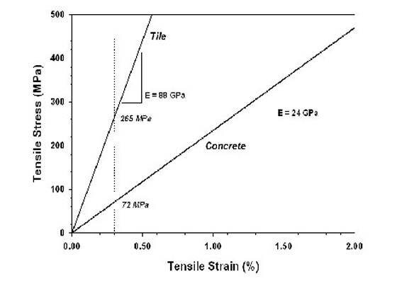
Figure 5
A stress-strain diagram illustrating the difference between typical concrete and a ceramic tile. Note the substantial difference in stress developed in the ceramic tile (264 MPa) and in the concrete substrate (72 MPa) at a similar strain level (0.3%). (Note that the typical failure strain levels for tile and concrete are 0.11%, so the strain level in this illustration exceeds typical failure strain levels by nearly a factor of two.)
The second approach views the problem as the amount of strain a material can sustain until failure occurs. In this case the amount of stress exhibited in a material is dictated by the amount of strain imposed. If the strain is sufficiently large, the critical stress is exceeded, resulting in failure. As before, the failure mechanisms are identical - the perspective is slightly different however. This perspective is ideal for interpreting tile installation failures (and successes).

Finally, the relationship between stress, s, and strain, e, is determined by the elastic modulus (or Young's modulus), E, following Hooke's law. The larger the elastic modulus, the larger the stress is developed (or necessary) for a given strain level. The elastic moduli for concrete and ceramic tile differ, as well as the elastic moduli for ceramic tile of different compositions. In more general terms, the greater the elastic modulus, the stiffer the material. These descriptions are generally used to describe tensile (or compressive) stresses but can also be used to describe shear behavior, in which the shear stress, t, is related to the shear strain, g, through the shear modulus, G. The equations for tensile and shear behavior are (see images):

In the case of tile installations, the strain level can be developed through a number of avenues, and as such, the strains are additive. As described above, these strains are proportional to stress levels, and when a critical amount of stress is developed, failure in the form of cracking or de-bonding takes place. There are several sources of strain in a tile installation, as discussed below.
Sources of strain in tile installations
There are several sources for strain generation within the tile layer. In addition to shear stresses (which, for the purposes of these discussions are always present), tensile or compressive stresses can be generated in the tile layer. The stress state can be extremely complicated for a variety of reasons, including the differences between the substrate and the tile, and because of the differences in the mechanical properties of the bonding layers. Examples of tensile (+) or compressive (-) stress sources are listed in Table I, denoted by sign, assuming a constant condition in the bonded phase. For example, contraction due to curing in a concrete substrate would generate compressive stresses in the tile layer, assuming no other stresses within the tile layer.
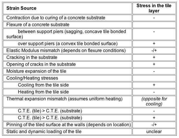
Table I
Sources of strain and the resulting stress in a tile layer. Tensile stresses are denoted with '+'; compressive stresses are denoted with '-'. Tensile stresses will lead to cracking of the tile layer; compressive stresses, under ideal conditions should not lead to cracking, but if sufficiently large, can cause the tile to buckle.
These strain development routes can be naturally grouped into two broad categories: tension and compression. In ceramics in general, compressive stresses are desired, but in the case of tile installations, as noted previously, excessive compressive stresses will produce buckling. However, in a directly bonded system, tensile stresses must be avoided, as they will almost always lead to cracking, either in the grout joint, the mortar bond coat, or in the tile. Even if small tensile stresses are present, cracking can occur in the bond coat, providing a location for future cracking of the tile surface - again, either within the tile itself or in the grout joints. In addition, significant shear stresses can develop between the tile and the bond coat, and/or between the bond coat and the substrate, leading to tile de-bonding.
Specifically, under tensile stress conditions within the tile, two problems can occur: 1) If the bond coat possesses a low shear strength, tensile stresses in the tile (and correspondingly compressive stresses in the bond coat) can create sufficient shear stress to cause shear failure in the tile-bond coat interface, and the tile will de-bond. 2) In conditions of high bond coat shear strength, de-bonding of the tile will not occur; the tensile strain is transferred to the tile, and tensile cracking of the tile results.
Similarly, under compressive stress conditions within the tile, compressive failure is unlikely (due to the fact that ceramics tend to be very strong in compression), so de-bonding of the tile occurs either by shear failure of the tile-bond interface, or by tensile failure of the bond coat through flexure of the tile. (Flexure of the tile away from the substrate will produce tensile stresses perpendicular to the tile surface.)
Allowance for stress development during the installation process has traditionally been compensated for by using the more recent analog of the sand strata method. There are two principle methods for executing this style of installation. One method is to install the tiles on a mortar screed that is still plastic. Immediately covering the freshly placed mortar with tile slows the rate of hydration in the mortar screed, thereby reducing the amount of stress exerted on the system due to shrinkage. The second method is to install the tiles using a dry-set mortar after the mortar screed has cured. Once the tiles are placed, the dry-set mortar is allowed to cure, thereby reducing the effects of shrinkage. If the tiles were installed before the mortar bed cured, additional residual stresses could develop in the tile layer, potentially leading to cracking. In addition, mortar mixes used in installations of this genre have traditionally been lean mixes to keep the internal stresses of the screed to a minimum.
Problems with cracked substrates
In cracked substrate situations, as the crack opens or closes, significant shear stresses develop which, depending on their direction, can generate tensile or compressive forces within the tile bed. Obviously, a cracked substrate represents one of the most dangerous potentials for tile installation failure.
Thermally activated stress development
Another factor is that thermal stresses generated by heating and cooling cycles are common, and thereby represent a dynamic fatigue potential. This situation is compounded by the fact that the concrete and the mortar probably do not have the same thermal expansion coefficient (CTE), that the tile CTE can vary significantly (depending on the type of tile used), and that the grout will have yet another CTE. Thermal stresses can be significant and as such, cannot be ignored.
Therefore, thermally activated strains can create significant stresses due to differences in CTE. Even a small CTE mismatch can lead to substantial strains when incurred over the distance between expansion joints. It should be noted that there can be a broad range of CTE's based on tile types (e.g. porcelain, terra cotta, etc.), thin-set mortars, joint fillers, and concrete.
As an example, a situation in which the concrete substrate and the mortar have the same CTE of 10 x 10-6/°C, and a typical tile has a CTE of 6 x 10⁻⁶/°C, produces a difference in CTE of Δ = 4 x 10⁻⁶/°C. If the concrete was 10°C warmer than the tile surface, this would produce a tensile strain in the tile layer of 0.04 mm/meter (40 μm/meter). Over a five meter span, this amounts to a strain of 0.2 mm (200 μm). Using the tile elastic modulus (88 GPa) shown in Figure 5, and assuming that all of the stress is concentrated in the tile layer (i.e., no stress in the concrete substrate), this would generate a tensile stress within the tile layer of 3.5 MPa. While this stress is probably not sufficient to directly cause failure, when combined with other residual stresses, it provides a significant contribution.
In the case of in-floor hydronic heating systems, systems where the heating tubes are overlaid with an approximately 2" mortar screed, there is a high potential for stress buildup within the system. For example, suppose the room to be heated is relatively cold, e.g. 10°C. It is not uncommon for the water temperature inside the heating tubes to reach 45°C to produce a desired temperature of 25°C on the surface of the tile. This results in a temperature differential of 35°C within the assembly. During the process in which the system develops its operating temperature, the lower portion of the screed is heated first and expands at a larger rate than the upper portion of the screed. Using the thermal properties detailed in the previous paragraph, a strain of 0.7 mm (700 μm) is developed over a five meter span, producing a stress within the tile of 12.3 MPa - even if only for a brief period of time.
In light of this, it becomes evident that a force-conductive bond between the tile and the screed is under considerable stress due to the strains imposed and, as such, it is reasonable to conclude that these strains are a significant contribution to tile installation failures over radiant heated floors.
Understanding stress buildup and reduction
The ceramic matrix composite analogy
Ceramic fiber reinforced ceramic matrix composites offer a "high-tech" analogy to the tile installation problem. In brittle matrix composites, if a strong bond develops between the fiber and the matrix, the composite will exhibit brittle failure. If the interface is weak, the fiber is able to deform independently of the matrix and, as such, can exhibit significant increases in toughness through the energy absorbing mechanisms of fiber pullout and crack deflection. The fiber-matrix interface must exhibit shear failure for the fiber to adequately de-bond and prevent catastrophic failure. Strong bonding leads to poor performance. In properly designed systems, it is not uncommon to observe cracking within the matrix but not in the fibers - in fact, the fibers bridge the cracks in the matrix, providing the appearance of an intact specimen.
It has also been demonstrated that fiber composites, when tested in bending (i.e., the modulus of rupture test) actually fail in a shear/compressive mode on the compressive side of the specimen, rather than in tension on the tensile side of the test specimen. The shear stresses developed during the test are significant, and, when coupled with the compressive stresses, lead to failure. This condition is analogous to the situation with rigidly bonded ceramic tile - a thin sheet of materials bonded strongly to a substrate, which can exhibit a (relatively) significant amount of bending during loading. Relieving the shear stresses would increase the strength of the sample.
In the case of small cross-section materials like fibers, the material is inherently more flexible because the strain developed in the fiber, even under substantial bending, usually does not exceed the strain limitations of the material. The same is true of tile/mortar/grout assemblages in uncoupled systems. The small cross section of the tile layer would naturally allow for greater flexibility, provided the strain limit is not exceeded. When the tile is rigidly bonded to the substrate, however, the strain is transferred to the tile through the bond coat and compounded by the combined thickness of the entire substrate-tile assembly. Once the strain limit of the tile is exceeded, fracture results. Allowing the tile layer to move independently of the substrate greatly increases the amount of flexure the substrate can accommodate without causing failure in the tile layer.
Large-scale tests on tile bonded to concrete slabs
Large-scale deflection experiments conducted at Cornell University (Ithaca, NY),1 on tile directly bonded to reinforced concrete slabs (6.7 x 1.2 meters, 20 cm thick), demonstrated that tile would de-bond when sufficient deformation of the slab was obtained. The strain exhibited in the tile, both on the tensile and compressive side of the beam, was amplified by its rigid bonding to the concrete. In the Cornell work, substantial strains were developed, sufficient to cause buckling of the tile layer on the compression side of the flexed slabs and de-bonding and cracking on the tensile side. One inference of the test was that obtaining greater shear strength in the bonding materials would have prevented de-bonding of the tile. Based on the analysis presented above, however, it would appear that the opposite would more likely be true. If the interface between the tile and the concrete substrate allowed the tile to flex independently of the substrate, a significant portion of the stresses would have been relieved, and the tile would have more likely withstood much greater deformations prior to de-bonding.
Flat membranes: Directly bonded "anti-fracture" and crack-isolation membranes
To date, there has been little analysis on the functioning principles of flat membranes presented to the tile installation community in general. Additionally, there is no accepted definition for "anti-fracture" within the tile industry. In principle, "anti-fracture" membranes would be applied over the entire surface to be tiled and should address most or all of the sources of strain or shape deformation encountered throughout the life of the installation.
Crack-isolation membranes, on the other hand, were designed to address existing cracks, or cracks that may develop in the future. They do not address the dynamics of the entire installation. These membranes consist of flat composite sheets or cold liquid trowel-applied materials that can be applied in two ways: 1) in narrow bands over existing cracks in the substrate (as illustrated in Figure 6), or 2) over the entire surface.
It should be noted that the tile industry refers to crack-isolation membranes and "anti-fracture" membranes as one in the same, though they are not. This is largely a marketing phenomenon.
"Crack-isolation", or flat membranes were initially developed as a means of preventing cracks from developing in the finished tile surface. However, there are several problems. Because these membranes are flat and very thin (30 - 40 mil) they are incorporated into the tile assembly in a force-conductive bond; thus the installation is left to the mercy of the strain development factors and the deformation of the substrate. What this means in practical terms, is that differential movement within a thin layer - meaning the upper and the lower portion of the membrane - is minimal at best. Additionally, the energy generated from these stresses is stored in the membrane because there is no free space incorporated into the assembly to accommodate them. One could argue, if a thicker membrane were used, that the elastic properties of the membrane could accommodate shear stresses. However, attempts in this direction have proven to be unsuccessful, due to the fact that the load bearing capacity was substantially reduced due to compressive flexure (perpendicular to the tile surface) of the membrane under static and dynamic loading conditions. In summary, it must be considered that a force-conductive bond still exists in this assembly. Therefore, it is difficult to measure or even estimate the effectiveness of current crack isolation membranes considering the multitude of possible stresses and the physical characteristics of the floor assembly. In this light, there is no reasonable way to establish meaningful guidelines for their use in today's building environment.
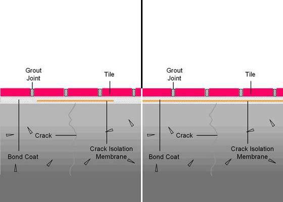
Figure 6
Schematic illustration of the two common approaches used with crack isolation membranes, or flat membranes. The diagram on the left shows the membrane used to directly address existing cracks in the substrate. The illustration on the right uses the crack isolation membrane over the entire substrate surface. The use of these membranes does not eliminate the force conductive bonding situation, which leads to cracking in the tile assembly due to strain transfer from the substrate.
Creating a forgiving shear interface
The sand strata analogy
The sand strata system provided a forgiving shear plane "naturally" as an unbonded granular mass. A granular solid, or packed bed, has a limited shear cohesion. In these systems, the shear strength is directly, but weakly, related to the confining pressure. In sand strata systems, the mortar layer is relatively thin (1.0-1.5 cm), but there is a distinct interface between the mortar bed and the sand layer. Even under the worst of circumstances, the mortar will infiltrate the sand layer to a limited extent, allowing a significant amount of freedom within the sand strata. Thus, assuming the tile is installed properly, the tile is "free" to move independently of the substrate. This is how, in many ancient installations, failure within the tile layer was avoided. The sand strata method provided an effective means of uncoupling the mortar bed through the poor cohesion afforded by a packed granular mass.
The only means of reducing stress buildup between the tile and the substrate is to create a forgiving shear plane, which allows movement within the bonding system plane. It is essential that the tile, mortar bed, and grout are able to move as a coherent sheet, independent of the substrate - that is, the mortar bed must be "uncoupled" from the substrate. Bonding the tile firmly to the substrate will force stress buildup and ultimately failure. The sand strata method or, more recently, the mortar bed method, effectively uncouples the mortar bed/tile assembly through a cleavage layer of sand or a cleavage membrane.
In addition, these systems provided an effective load-distribution plane, allowing normal live load forces exerted on the tiled surface to be widely distributed throughout the assembly. Modern tile installations demand a similarly reliable shear interface. However, due to the design requirements in today's building environment, the shear interface must necessarily be lightweight, compact, and easy to install.
The uncoupling of a configured membrane
Creating a forgiving shear plane through the use of a configured polyethylene sheet-applied membrane, which is mechanically bonded to both the substrate (through a thin mortar bond coat) and the tile, has provided tile installers a solution to the problem.
The fleece, or scrim, on the underside of the membrane, or matting, establishes a mechanical bond to the dry-set mortar applied to the substrate. The cutback, cavity design of the upper side of the matting establishes a mechanical bond to the tile. The system allows the tile to be locked to the substrate in the vertical direction, while allowing relatively large in-plane motion. By allowing this motion, the system also allows for movement within cracks and behaves not unlike a shear interface created by an unbonded granular mass, as evinced with the sand strata method. Moreover, it allows the normal loading forces exerted on the tile surface to be widely distributed throughout the assembly.
The rib structure allows for free space within the bonding layer. This space is essential to provide flexibility within the bonding plane, providing greater freedom for the relief of stresses. In addition, this free space provides air channels between the membrane and the substrate, thus allowing any residual moisture in the substrate to evaporate and, thereby, permitting vapor equalization within the system. This is particularly important in today's building environment where most - if not all - tile substrates are moisture sensitive.
The most significant aspect of this solution, however, is that the objective has been achieved without the use of a force-conductive bond, thus neutralizing the vast majority of stresses in a tile installation. This does not suggest (nor is there any evidence from the field) that the tile assembly should be weakly bonded to the floor, or that the tile should be easily removed, but that the installation system allows for in-plane motion.
As pointed out previously in the analogy for thermal stress development, the system would need to allow for significant motion (under certain conditions estimated to be 700 μm over a five-meter distance) in the plane of the installation. Therefore, the use of expansion joints, with the expressed intention of allowing thermally generated stresses to be dissipated, is still a necessary part of tile installation.
Conclusions
In conclusion, ceramic tiles are hard, brittle, and unforgiving materials and, as such, are dependent upon the dimensional stability of the assembly to which they are bonded. Movement forces are present in all tile installations due to the dimensional instability of the structural components that make up the assembly. Analysis of the mechanical properties of composite systems tells us that these forces manifest themselves at the shear plane or material interfaces of the tile sandwich. In this light, failure is likely to result if the components of the tile assembly are joined together in a force-conductive bond.
The methods of installing ceramic tile have changed over the years. However, the physical dynamics of a tile assembly have not. Traditional installation methods addressed these dynamics by uncoupling the tile covering from the building structure through the use of a sand stratum or a mortar bed placed over a slip-sheet. Today, uncoupling the tile covering from the substrate can be achieved in a contemporary thin-bed application through the use of a configured, polyethylene sheet-applied membrane. This installation approach does not eliminate the need for skilled tile installers, nor does it allow poor quality workmanship. What it does is provide the opportunity for reliable tile installations on problematic substrates.